Introduction
In the ever-evolving world of electronics, understanding through-hole PCB assembly is essential for anyone looking to dive into the intricate realms of circuit boards and components. This method, characterized by inserting component leads through holes in a printed circuit board (PCB), has stood the test of time due to its reliability and ease of use. Whether you’re a hobbyist or a seasoned engineer, mastering soldering through hole techniques can elevate your projects to new heights.
Understanding Through-Hole PCB Assembly
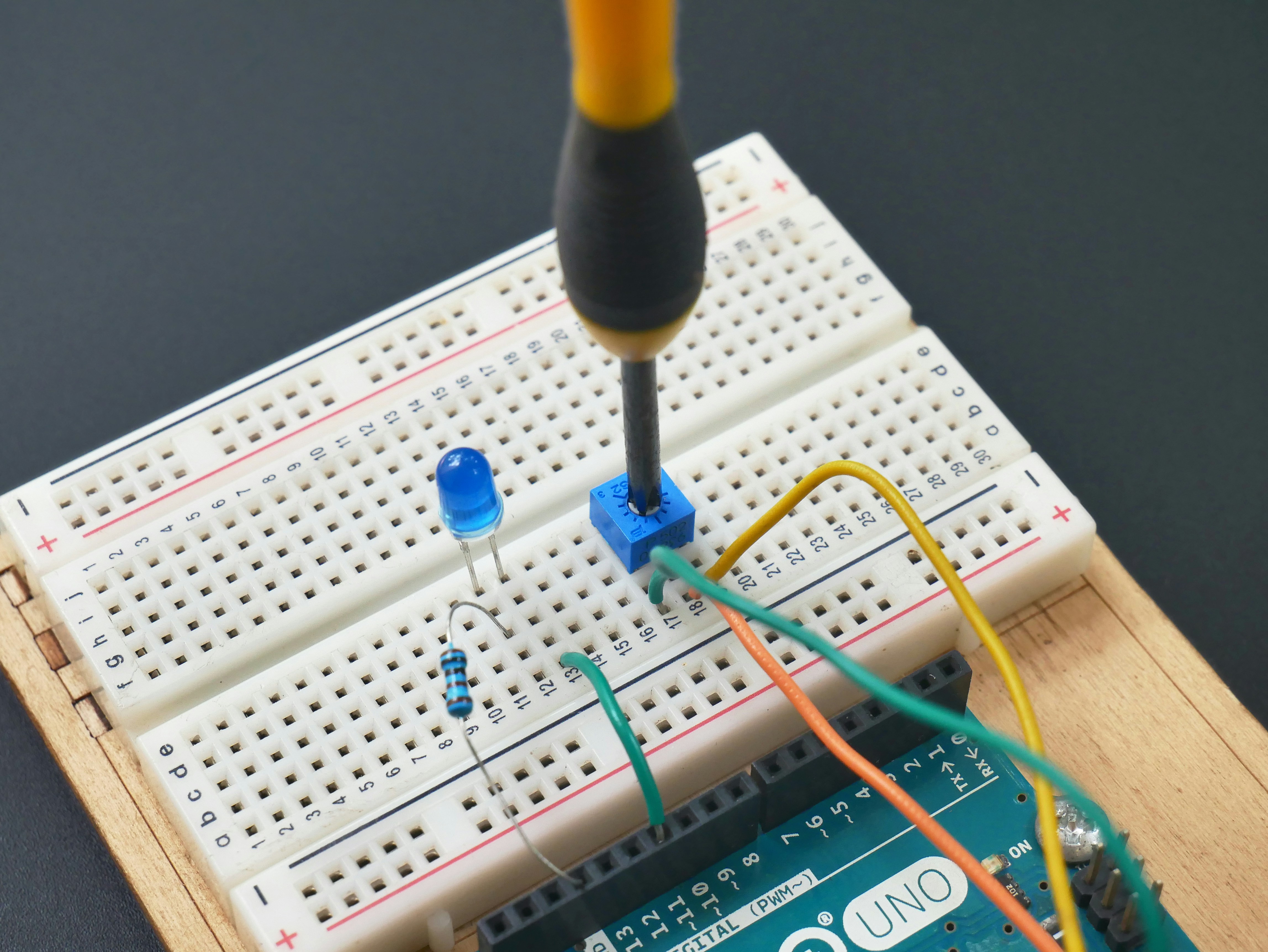
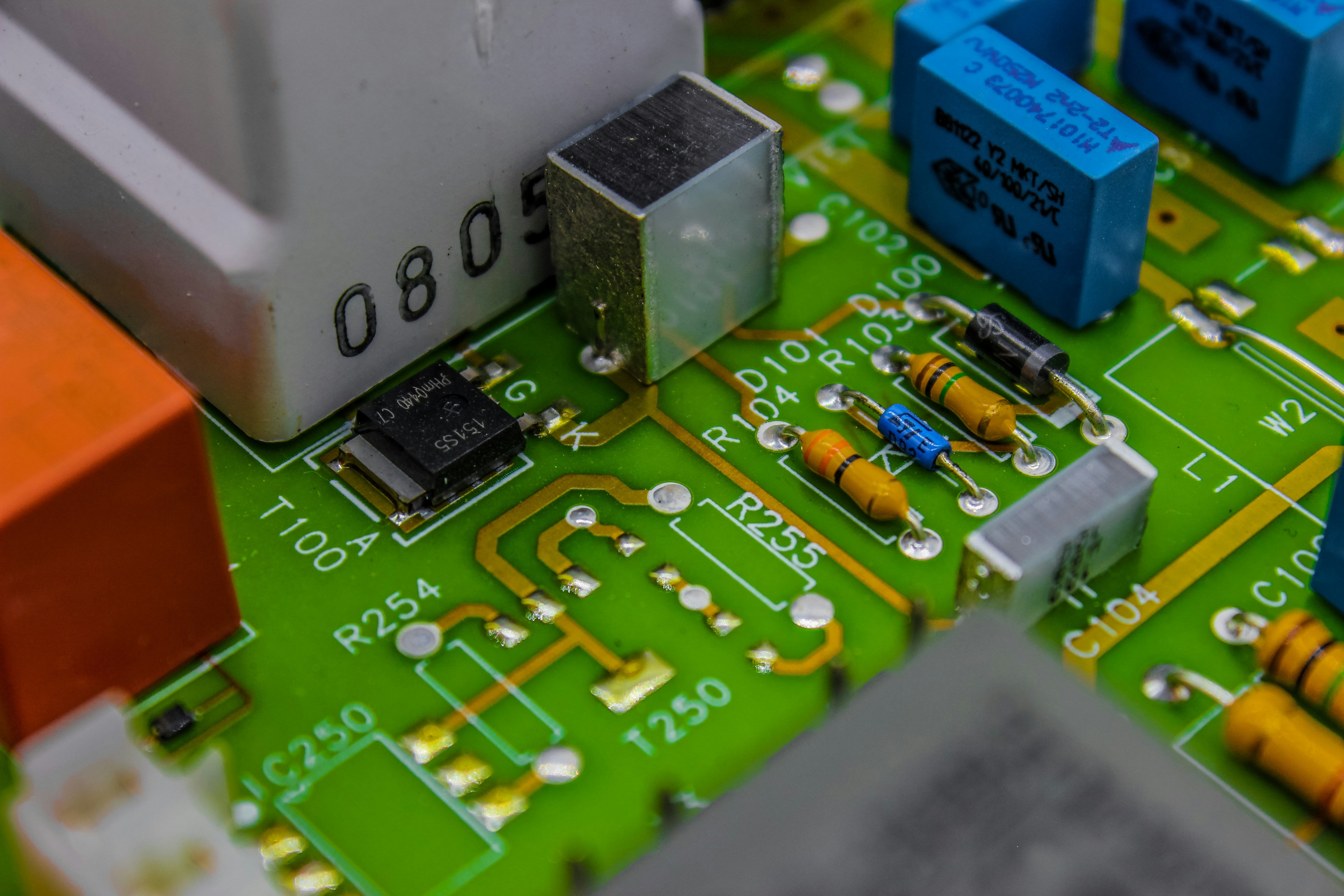
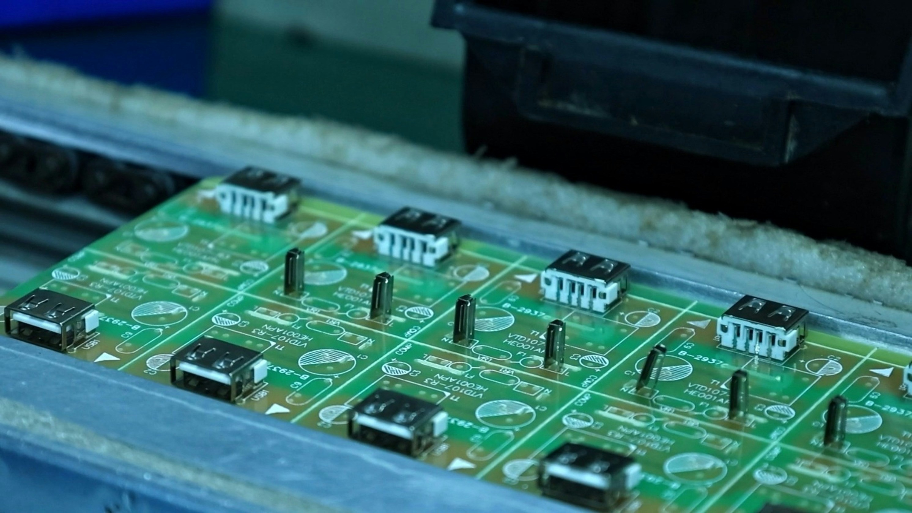
Through-hole PCB assembly involves the insertion of electronic components with leads that pass through holes drilled in a circuit board. This traditional method is often favored for its robustness, making it ideal for applications requiring high durability and mechanical strength. By using a circuit board soldering iron, you can create strong connections that withstand vibrations and thermal stress better than many alternatives.
The Evolution of Soldering Techniques
Soldering techniques have come a long way since their inception, evolving from simple manual processes to sophisticated automated systems. Initially dominated by lead-based solders, the industry has shifted towards lead-free solder options to meet environmental standards and regulations. Despite these advancements, soldering through hole remains popular due to its straightforward approach and compatibility with various circuit board components.
Benefits of Through-Hole Components
One significant advantage of through-hole components is their ability to handle larger currents and voltages compared to surface mount technology (SMT) counterparts. Additionally, the physical structure allows for easier repairs and modifications on assembled PCBs—a crucial factor when working on complex projects or prototypes. Furthermore, using a quality PCB soldering iron ensures that connections are not only reliable but also maintainable over time.
Overview of Through-Hole PCB Assembly

Through-hole PCB assembly is a traditional method that involves inserting component leads into holes drilled in a circuit board and soldering them in place. This technique is particularly important for creating durable connections, as it provides mechanical strength and stability to circuit board components. While newer methods like surface mount technology (SMT) have gained popularity, through-hole assembly remains essential for specific applications due to its reliability.
Definition and Importance
Through-hole assembly refers to the process of soldering components with leads that pass through holes in a printed circuit board (PCB). This method is crucial because it ensures robust electrical connections, making it ideal for high-stress applications where reliability is paramount. The use of a circuit board soldering iron allows for precise control during the soldering process, ensuring that lead free solder bonds effectively with the metal pads on the board.
Common Applications in Electronics
Through-hole PCB assembly finds its niche in various electronic applications, particularly where durability and repairability are critical. You’ll often see this technique employed in power supplies, audio equipment, and military electronics that demand robust performance under challenging conditions. Additionally, many DIY enthusiasts prefer using through-hole components because they are easier to handle and provide clear visual feedback during circuit board soldering.
Comparison with Surface Mount Technology
When comparing through-hole assembly with surface mount technology (SMT), several key differences emerge that can influence project decisions. Through-hole components tend to be larger and require more space on the circuit boards and components layout than their SMT counterparts. However, while SMT allows for higher density designs and faster production speeds, through-hole techniques excel in providing mechanical strength and ease of repair—making them indispensable when durability matters most.
Essential Tools for Through-Hole PCB Assembly

When it comes to through-hole PCB assembly, having the right tools is crucial for achieving a high-quality result. From the soldering iron to the solder itself, each component plays a vital role in ensuring that circuit boards and components function correctly. Let’s delve into the essentials that will make your soldering through hole experience efficient and effective.
Choosing the Right PCB Soldering Iron
Selecting the right PCB soldering iron can make all the difference in your assembly process. A good soldering iron should have adjustable temperature settings to accommodate different types of solder and circuit board components. Look for one with a fine tip, as this allows for precision when working on intricate circuit boards and components, ensuring clean connections without risking damage.
Moreover, consider ergonomics; a comfortable grip will help reduce fatigue during longer projects. Remember, investing in a quality circuit board soldering iron is not just about immediate results—it's about enhancing your skills over time and achieving consistency in your work. With the right tool in hand, you'll find that soldering through hole becomes less of a chore and more of an art form.
Lead Free Solder Options
Lead-free solder has gained popularity due to its environmental benefits and compliance with safety regulations. When choosing lead-free options for your through-hole projects, look for solders that provide good flow characteristics while maintaining strong joints on circuit boards and components. Common types include SAC (tin-silver-copper) alloys which are known for their reliability in various applications.
While working with lead-free solder may require slightly higher temperatures compared to traditional leaded options, many modern PCB soldering irons can easily accommodate this change. It’s essential to familiarize yourself with different lead-free formulations as they can vary significantly in terms of melting point and performance during assembly. Ultimately, using lead-free solder not only supports eco-friendly practices but also ensures you’re ready for future industry standards.
Must-Have Accessories for Efficient Assembly
To complement your PCB soldering iron and enhance your overall efficiency during through-hole assembly, certain accessories are invaluable additions to your toolkit. First on the list is a quality pair of tweezers; these are perfect for handling small circuit board components without causing damage or contamination to sensitive areas of the board.
Next up is a reliable flux pen or paste; applying flux before soldering can significantly improve adhesion between surfaces—making those connections stronger than ever! Finally, don’t overlook safety gear such as anti-static wrist straps; these protect both you and your delicate electronic parts from static discharge while working on intricate projects.
Incorporating these accessories into your workflow will streamline processes and minimize errors during assembly—a win-win situation! With these tools at hand, you’ll be well-equipped to tackle any challenge that comes with assembling circuit boards using through-hole technology.
Techniques for Effective Soldering Through Hole

When it comes to soldering through hole components, mastering the right techniques can make all the difference in achieving a reliable and clean connection on your circuit boards. Whether you’re a seasoned pro or a beginner, understanding the step-by-step soldering process is essential. Let’s dive into effective strategies that will help you navigate the world of through-hole PCB assembly with ease.
Step-by-Step Soldering Process
The first step in soldering through hole components is to prepare your workspace and gather your tools, including a quality PCB soldering iron and lead-free solder. Start by inserting the component leads through the designated holes on the circuit board; ensure they are snugly fit to prevent movement during soldering. Once positioned, heat the joint with your soldering iron while simultaneously feeding in lead-free solder until it flows around the lead and onto the pad, creating a solid connection.
After you’ve made your first joint, allow it to cool for a few seconds before trimming any excess leads with wire cutters. Repeat this process for each component on your circuit board, ensuring that you maintain proper technique throughout to avoid cold joints or bridges between connections. Finally, inspect each joint visually; a good solder joint should have a shiny appearance and be smooth without any gaps or excessive buildup.
Tips for Handling Circuit Board Components
Handling circuit board components requires care and precision to ensure that everything fits perfectly into place without damage. Always use tweezers when positioning smaller components; this minimizes contamination from oils on your fingers and reduces the risk of bending leads out of shape. Additionally, keep an organized workspace—this means having all necessary tools like your circuit board soldering iron within reach but not cluttered around sensitive components.
When working with delicate parts or multi-lead devices, consider using fixtures or jigs to hold them securely during assembly; this can drastically improve accuracy while reducing frustration. If you're using lead-free solder—which tends to have higher melting points than traditional options—make sure your iron is set at an appropriate temperature to avoid damaging sensitive parts while achieving effective heat transfer during soldering through hole processes.
Troubleshooting Common Soldering Issues
Even experienced technicians encounter challenges when it comes to circuit board assembly; knowing how to troubleshoot common issues can save time and materials in the long run. One frequent problem is cold joints—these occur when insufficient heat is applied during soldering through hole connections, resulting in weak electrical conductivity. To fix this issue, reheat the joint carefully while adding more lead-free solder if necessary until you achieve that desirable shiny finish.
Another common concern is bridging between adjacent pads due to excess molten solder pooling together; this can often be resolved by gently reheating the area with your PCB soldering iron then using desoldering braid or a pump tool to remove excess material carefully without damaging surrounding components. Lastly, if you're struggling with component misalignment after insertion into circuit boards and components are not fitting correctly, double-check their orientation against schematics before applying heat—correct placement ensures optimal performance once assembled.
Best Practices for Quality Control
In the world of soldering through hole, maintaining high standards of quality control is crucial for ensuring the longevity and reliability of circuit boards and components. As technology evolves, so too do the methods used to inspect and verify the integrity of solder joints and overall assembly. Implementing best practices in quality control not only enhances product performance but also builds trust with customers.
Importance of Visual Inspection Machines
Visual inspection machines play a vital role in the quality control process for circuit board soldering. These machines are designed to detect defects such as insufficient solder, misaligned components, or cold solder joints that may compromise functionality. By incorporating visual inspection into your assembly line, you can catch errors early on and reduce costly rework or product failures down the line.
Ensuring Reliability with Proper Equipment
To guarantee reliable results in through-hole PCB assembly, using the right equipment is essential. A high-quality PCB soldering iron ensures precise application of lead free solder while minimizing damage to sensitive circuit board components. Investing in reliable tools not only streamlines your workflow but also significantly reduces the risk of defects that can arise from using subpar equipment.
Bensun's Role in Quality Assurance
Bensun has established itself as a leader in quality assurance within the PCB assembly industry by providing top-notch inspection solutions tailored for through-hole techniques. Their advanced visual inspection systems are designed to work seamlessly with various types of circuit boards and components, ensuring that every joint meets stringent standards before reaching consumers. By partnering with Bensun, companies can enhance their quality control processes and deliver products that inspire confidence among users.
[Image description=visual inspection machine scanning a printed circuit board on an assembly line, bright LED lights illuminating details, technician monitoring output on a screen, sophisticated machinery at work], Image name=visual_inspection_machine_circuit_board_assessment, Alt tag=soldering through hole quality assurance visual inspection machine
When to Choose Through-Hole Assembly

Through-hole assembly remains a popular choice in various electronic projects, especially when certain conditions favor its use. Understanding when to opt for this method involves evaluating the size and configuration of components, specific project requirements, and cost implications. This section will guide you through these considerations, ensuring that your circuit board assembly is both efficient and effective.
Assessing Component Size and Configuration
Larger components or those requiring robust mechanical support are often better suited for through-hole techniques due to their ability to withstand physical stress. Additionally, if you're working with components that have longer leads or need precise placement on the circuit board, a soldering through hole approach can provide the stability necessary for optimal performance.
It's also important to assess how densely packed your circuit boards will be; if you're dealing with larger or more complex designs, through-hole technology may offer advantages over surface mount options. The depth of the holes in your PCB can also impact component fit; ensure that your circuit board soldering iron can reach these areas effectively without damaging surrounding components. Ultimately, careful consideration of component characteristics will help you determine whether through-hole assembly is the right choice for your project.
Situations Favoring Through-Hole Techniques
There are specific scenarios where choosing through-hole techniques makes perfect sense. For instance, high-stress applications such as automotive or aerospace electronics often require the durability that only soldered connections can provide; here, lead-free solder used in conjunction with a reliable PCB soldering iron ensures compliance with safety standards while maintaining structural integrity. Moreover, when designing prototypes or educational projects where ease of handling is crucial, through-hole assembly allows for straightforward modifications and repairs.
If you're working on projects involving heavy-duty connectors or capacitors that experience significant thermal cycling during operation, through-hole connections excel at managing these stresses compared to their surface-mounted counterparts. Additionally, if you anticipate needing frequent repairs or alterations on your circuit boards and components over time, having accessible leads from a soldering iron makes maintenance easier than dealing with tightly packed surface mount parts. In these situations, opting for through-hole assembly not only simplifies construction but also enhances long-term reliability.
Cost Considerations for Different Projects
Cost is always a key factor when deciding between assembly methods; thus it's essential to evaluate how using soldering through hole affects overall project expenses. Generally speaking, while initial costs may be higher due to more labor-intensive processes involved in inserting component leads into holes before soldering them down securely—especially compared with faster surface mount technology—the long-term benefits often outweigh these upfront investments. The durability offered by lead-free solders in conjunction with robust connections translates into fewer failures down the line.
Additionally, consider production volume: if you're producing small batches or custom designs where precision matters more than speed and cost efficiency isn't as critical—through-hole methods shine brightly here! On the other hand, high-volume production runs may benefit from switching gears towards surface mount techniques despite potential quality trade-offs since they allow quicker manufacturing cycles overall at lower costs per unit produced. Ultimately assessing both immediate expenses alongside future operational needs will guide you toward making an informed decision about which assembly method suits best!
Conclusion
In wrapping up our exploration of through-hole PCB assembly, it’s clear that this technique offers a wealth of advantages for electronics enthusiasts and professionals alike. By leveraging the strengths of soldering through hole components, we can create robust and reliable circuit boards that stand the test of time. As we look to the future, it’s essential to embrace both traditional methods and emerging technologies to maximize efficiency and quality in our projects.
Maximizing Benefits of Through-Hole Assembly
To truly capitalize on the benefits of through-hole assembly, one must understand its unique capabilities in various applications. Soldering through hole connections not only provides mechanical strength but also allows for easier repair and modification of circuit board components. This is particularly advantageous in industries where durability is paramount, ensuring that your circuit boards and components can withstand rigorous use.
Moreover, using a high-quality PCB soldering iron paired with lead-free solder enhances the overall performance of your assembly process. With increasing environmental regulations pushing for greener practices, lead-free solder options have become essential in modern electronics manufacturing. By prioritizing these materials, you ensure compliance while also contributing positively to global sustainability efforts.
Future Trends in PCB Techniques
The landscape of PCB techniques is continually evolving, with innovations aimed at improving efficiency and reducing costs making headlines every day. One trend gaining traction is the integration of automation into traditional soldering processes; robots equipped with advanced soldering tools are beginning to take on tasks previously reserved for skilled technicians. This shift not only speeds up production but also reduces human error during circuit board soldering.
Additionally, advancements in materials science are leading to new types of lead-free solder that offer superior performance characteristics compared to their predecessors. These innovations promise enhanced thermal stability and better adhesion properties when used with a circuit board soldering iron, making them ideal for high-performance applications. As we move forward, staying informed about these trends will be crucial for anyone involved in PCB assembly.
Final Thoughts on Soldering and Components
In conclusion, mastering the art of soldering through hole components opens up a world of possibilities in electronic design and manufacturing. Whether you're a hobbyist or a seasoned professional working with circuit boards and components daily, understanding best practices will significantly enhance your results. Embracing both traditional techniques like through-hole assembly alongside modern innovations ensures that you remain competitive while producing top-notch electronic products.
As you embark on your next project involving circuit board assembly, remember the importance of quality tools such as a reliable circuit board soldering iron and appropriate lead-free solder options at your disposal. The combination of skillful application and cutting-edge materials will undoubtedly lead to successful outcomes in all your electronic endeavors.
